In CHAI3D, a polygon mesh is a collection of vertices and triangles that define the shape of a polyhedral object.
A vertex is a position along with other information such as color, normal vector and texture coordinates. Two vertices connected by a straight line become an edge. Three vertices, connected to each other by three edges, define a triangle, which is the simplest polygon in Euclidean space.
Mesh objects may be translated, rotated, or resized, and have one material and texture property assigned to them.
The following code illustrates how to create a textured square composed of 4 vertices and 2 triangles.
In the following section we review the different rendering options offered in CHAI3D:
Material properties define how a surface reflects light. They do this by defining color values much the same way that lights do. A material has a color values for diffuse (direct) light, ambient (scattered) light, and specular (reflected) light, but these values define how the components of light are reflected off the material surface. More information can be found in the section about materials.
The material property can be enabled or disabled, and requires the use of at least one light source in the world for the object to be visible.
Different color values can be specified for each vertex of the mesh. If three vertices of a triangle share different colors, then the color at any point on the triangle is computed through interpolation of the three vertex colors.
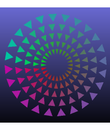
If the material property is enabled, vertex colors are combined with the material color. It is common to set the material to white and assign colors to the different vertices to produce a desired light shading. If the material property is disabled, then all light sources are ignored and the pure vertex color is used to render the object.
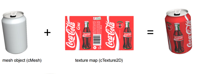
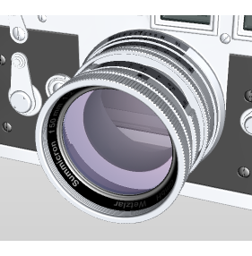
A texture map is applied (mapped) to the surface of a shape or polygon. This process is akin to applying patterned paper to a plain white box. Every vertex in a polygon is assigned a texture coordinate (which in the 2d case is also known as a UV coordinate) either via explicit assignment or by procedural definition. Image sampling locations are then interpolated across the face of a polygon to produce a visual result that seems to have more richness than could otherwise be achieved with a limited number of polygons.
To understand how to create a texture in CHAI3D, see the first example at the top of this page.
Triangles can be rendered in either solid or wire mode.
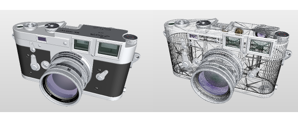
To render edges and triangles simultaneously, CHAI3D offers the option to display the triangles and overlay a subset of edges that are selected according to a desired minimum angle between adjacent triangles.
Back-face culling determines whether a triangle of a mesh object is visible. It is a step in the graphical pipeline that tests whether the vertices in the triangle appear in clockwise order when projected onto the screen.
If face culling is enabled, but the polygon projected on the screen has a counter-clockwise winding then it has been rotated to face away from the camera and will not be drawn.
The process makes rendering objects quicker and more efficient by reducing the number of polygons for the program to draw. For example, in a city street scene, there is generally no need to draw the polygons on the sides of the buildings facing away from the camera; they are completely occluded by the sides facing the camera.
In general, back-face culling can be assumed to produce no visible artifact in a rendered scene if it contains only closed and opaque geometry. In scenes containing transparent polygons, rear facing polygons may become visible through the process of alpha composition.
A transparent physical material shows objects behind it as unobscured and doesn't reflect light off its surface. Clear glass is a nearly transparent material. Although glass allows most light to pass through unobscured, in reality it also reflects some light. A perfectly transparent material is completely invisible.
A translucent physical material shows objects behind it, but those objects are obscured by the translucent material. In addition, a translucent material reflects some of the light that hits it, making the material visible. Physical examples of translucent materials include sheer cloth, thin plastic, and smoked glass.
Transparent and translucent are often used synonymously. Materials that are neither transparent nor translucent are opaque.
Blending is OpenGL's mechanism for combining color already in the framebuffer with the color of the incoming primitive. The result of this combination is then stored back in the framebuffer. Blending is frequently used to simulate translucent physical materials. One example is rendering the smoked glass windshield of a car. The driver and interior are still visible, but they are obscured by the dark color of the smoked glass.
When lighting is enabled in CHAI3D, the normal vectors are used to determine how much light is received at the specified vertex or surface. If the surface normals have not been defined, they can be computed for every triangle by taking the vector cross product of two edges of that triangle.
For debugging purposes, surface normals can be displayed using the following calls:
Since mesh objects only contains a single material and texture property each, creating meshes that use a collection of materials and textures requires using a different class called cMultiMesh which concatenates a list of meshes together. By organizing triangles according to their material and texture property in separate mesh objects, it is possible to efficiently build and render complex objects with a rich set of properties.
CHAI3D supports 3DS, OBJ, and SLT file formats to import or export models. If you wish you import files of a different format, you can use applications such as Blender or Visual Enterprise Author (formerly known as Deep Exploration) to edit and convert files to desired formats.
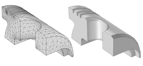
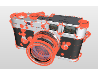
A collision detector is used to compute the intersection between a ray and any of the triangles that compose a mesh (or multi-mesh). In order for this operation to proceed quickly, CHAI3D uses a bounding volume hierarchy or BVH. A BVH is a tree structure on a set of geometric objects. All geometric objects are wrapped in bounding volumes that form the leaf nodes of the tree. These nodes are then grouped as small sets and enclosed within larger bounding volumes. These, in turn, are also grouped and enclosed within other larger bounding volumes in a recursive fashion, eventually resulting in a tree structure with a single bounding volume at the top of the tree. Bounding volume hierarchies are used to support several operations on sets of geometric objects efficiently, such as in collision detection for haptic interaction computation, ray tracing, or mouse selection.
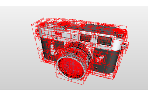
In CHAI3D, bounding volume hierarchies must be generated after the triangles have been defined. If the triangles are modified, or vertices moved, then the hierarchy must be computed again. When updating the collision tree, it is important to correctly include the radius of the largest haptic point used in the world. This information is used to create an envelope large enough to detect any interaction with contact points that have a radius smaller or equal to the defined threshold.
To haptically render mesh objects, CHAI3D uses a virtual "finger-proxy" algorithm developed by Ruspini and Khatib, similar to the "god-object" proposed by Zilles and Salisbury. The virtual proxy is a representative object that substitutes for the physical finger or probe in the virtual environment.
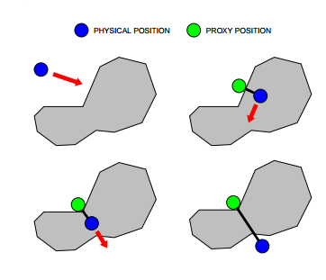
The above figure illustrates the motion of the virtual proxy, as the haptic devices's position is altered. The motion of the proxy attemps to always move toward a goal. When unobstructed, the proxy moves directly towards the goal. When the proxy encounters an obstacle, direct motion is not possible, but the proxy may still be able to reduce the distance to the goal by moving along one or more of the constraint surfaces. The motion is chosen to locally minimize the distance to the goal. When the proxy is unable to decrease its distance to the goal, it stops at the local minimum configuration. Forces are computed by modelling a virtual spring between the position of the haptic device and the proxy. The stiffness of the spring is defined in the material property.
Additional haptic effects can also be activated and adjusted through the material property class. Haptic effects use potential field algorithms which are also supported on any generic shape object. Please note that the magnetic effect is not currently supported on mesh objects.

