Cameras are the main viewing tools in 3D visualisation. They are placed in the world and named uniquely. Multiple cameras can exist in a scene, each one connected to a separate viewport (window) to show the user around the scene. Cameras can look at a fixed target, follow a path, or be controlled directly by a haptic device (e.g. to simulate an endoscope). This chapter explores the basic process of working with cameras and interfacing them to window displays, or viewports.
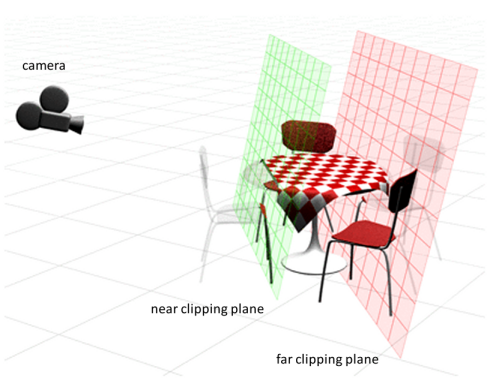
In the following example we create and insert a virtual camera inside a world. The position of the camera, a desired target point, and a vector defining where is "up", are used to intuitively position and orientate the camera within the scene. Controlling a camera by directly adjusting the local position vector and local rotation matrix is possible too. Note that a camera can also become a child of an object, or haptic tool. Near and far Clipping planes are used to define the active volume in which objects are rendered. Objects located outside the clipping planes are ignored and therefore not rendered to the display viewport. The location of each clipping plane is measured along the camera's line of sight in the current units for the scene. It is important to ensure that both the Near and Far clipping planes are set correctly and in a way that provides adequate depth buffer precision.
Orthographic, or parallel, projections consist of those that involve no perspective correction. There is no adjustment for distance from the camera made in these projections, meaning objects on the screen will appear the same size no matter how close or far away they are. In CHAI3D, the orthographic view is defined by assigning the physical width of the environment to be displayed to the viewport.
Although orthographic projections can be interesting, perspective projections create more realistic looking scenes, so that's what you will most likely be using most often. In perspective projections, as an object gets farther from the viewer it will appear smaller on the screen, an effect often referred to as foreshortening.

In 3D computer graphics, a viewport refers to the 2D rectangle used to project and render the 3D scene to the position of a virtual camera. A viewport is a region of the screen used to display a portion of the total image to be shown. The software code that is used to define a viewport display will always be specific to the operating system or GUI framework used to develop your application. The examples provided with CHAI3D use the FreeGLUT framework. More advanced applications may typically use the Qt framework. In both cases, setting up the window and display context is handled by the display manager itself.
Rendering the view from a camera is performed by simply calling the render() method of the camera. The minimum arguments that need to be passed are the width and height in pixels of the viewport or window display. The following listing illustrates a typical display callback from the GLUT window.
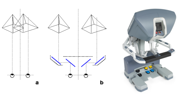
Stereopsis is the impression of depth that is perceived when a scene is viewed with both eyes by someone with normal binocular vision. Binocular viewing of a scene creates two slightly different images of the scene in the two eyes due to the eyes' different positions on the head. These differences, referred to as binocular disparity, provide information that the brain can use to calculate depth in the visual scene, providing a major means of depth perception.
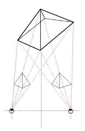
Because our two eyes are separated horizontally, on average by about 65 mm, each has a slightly different view of the world. The basis of stereo vision, stereopsis ("solid seeing"), is the angular horizontal disparity between corresponding points of an object in the two retinal images. When you fixate a point in a scene, your eyes rotate, or "converge", to bring the point of fixation onto the fovea of each retina. There is zero retinal disparity in the depth "plane" defined by the point of fixation. A point on an object that lies farther away from you than the fixation point creates images on the two retinas that have positive or uncrossed retinal disparity, determined by the angular of the corresponding points from the fovea on the two retinas. Similarly, points on an object that lies closer to you than the fixation point creates retinal images that have negative or crossed retinal disparity. The sign and magnitude of the retinal disparity are sufficient for the visual system to determine an object's depth relative to the point of fixation.
There are two prominent methods for displaying stereoscopic images using computers: active and passive. Both methods are supported under CHAI3D with a number of possible configurations.
The active display operates by very rapidly alternating between the left-eye and the right-eye image in the same space. Usually, this is done at about twice the frame-rate necessary for continuity of motion (120Hz). Special glasses must be worn in order to view this method. These glasses have lenses which turn from opaque to transparent in perfect sync with the change of image. The left image is only displayed when the left lens is transparent (and the right one is opaque) and vice versa. To use active quad-buffered stereo rendering under OpenGL you will be required to install a professional-grade graphics card that supports it, such as NVidia Quadro series, Oxygen's, Wildcats, etc.
Beside the stereo capable OpenGL graphics card, active stereo requires a monitor with a high refresh rate (100-160 HZ) and active shutter glasses connected to the video output / or stereo connector output. Alternatives include head mounted displays or stereo capable projectors.
A typical a hardware setup designed for active stereo rendering is summarized here:
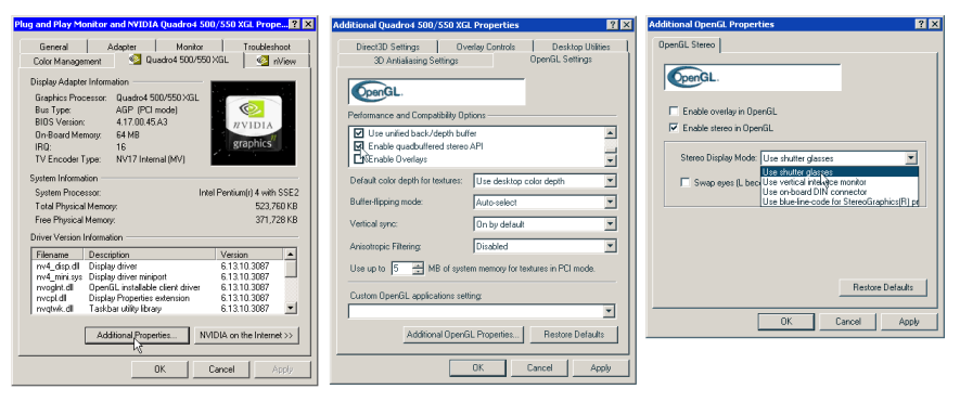
In the driver's control panel settings, OpenGL stereo support must be enabled. Here is an example configuration dialog for an Nvidia Quadro card:
On the software side of things, the display context must be configured to enable quad-buffer support, and active stereo must also be enabled at the camera level. The following listing illustrates how active stereo quad-buffer is configured using a GLUT window display. If you are using Qt for instance, stereo is enabled through the QGLFormat descriptor.
The passive method of displaying stereoscopic images is better suited for large groups, since the expensive technology is primarily in the display rather than each pair of glasses. The concept is simple; project both the left eye and the right eye simultaneously into the same space, and then use a special set of glasses which shows each image to its intended eye while blocking out the unintended image from that eye.

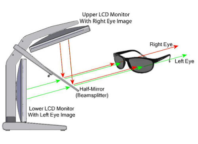
Systems in which both left and right eye images are simultaneously conveyed to the intended eye through independent channels are said to be spatially multiplexed. One approach uses two separate display monitors, each dedicated to just one of the two images. One current system, Planar StereoMirror, places one monitor above the other in a clamshell configuration with a half-silvered glass plate bisecting the angle between the two displays. The image on the lower monitor is seen transmitted through the glass plate, while the image on the upper monitor is seen reflected off the glass plate. The images emitted by the two monitors are cross-polarized and the observer wears passive cross-polarized glasses so that each eye sees only one of the two images. Limitations of this type of system are the need for careful alignment of the two monitors to exactly register the two images and, again, the reduction in the luminance of the light transmitted through the polarized glasses. Typically, linear polarization is used, which will result in ghosting if the observer tilts his/her head away from level.
For any branch of stereoscopy, the concept of the stereo window is important. If a scene is viewed through a window the entire scene would normally be behind the window: if the scene is distant, it would be some distance behind the window; if it is nearby, it would appear to be just beyond the window. An object smaller than the window itself could even go through the window and appear partially or completely in front of it. The same applies to a part of a larger object that is smaller than the window.
The goal of setting the stereo window is to duplicate this effect.
To truly understand the concept of window adjustment it is necessary to understand where the stereo window itself is. In the case of projected stereo, including "3D" movies, the window would be the surface of the screen. With printed material, the window is at the surface of the paper. When stereo images are seen by looking into a viewer the window is at the position of the frame. In the case of Virtual Reality the window seems to disappear as the scene becomes truly immersive.
In the case of paired images, moving the images further apart will move the entire scene back, moving the images closer together will move the scene forward. Note that this does not affect the relative positions of objects within the scene, just their position relative to the window. Similar principles apply to anaglyph images and other stereoscopy techniques.
There are several considerations in deciding where to place the scene relative to the window.
First, in the case of an actual physical window, the left eye will see less of the left side of the scene and the right eye will see less of the right side of the scene, because the view is partly blocked by the window frame. This principle is known as "less to the left on the left" or 3L, and is often used as a guide when adjusting the stereo window where all objects are to appear behind the window. When the images are moved further apart, the outer edges are cropped by the same amount, thus duplicating the effect of a window frame.
Another consideration involves deciding where individual objects are placed relative to the window. It would be normal for the frame of an actual window to partly overlap or "cut off" an object that is behind the window. Thus an object behind the stereo window might be partly cut off by the frame or side of the stereo window. So the stereo window is often adjusted to place objects cut off by the window behind the window. If an object, or part of an object, is not cut off by the window then it could be placed in front of it and the stereo window may be adjusted with this in mind. This effect is how swords, bugs, flashlights, etc. often seem to "come off the screen" in 3D movies.
If an object which is cut off by the window is placed in front of it, an effect results that is somewhat unnatural and is usually considered undesirable - often called a "window violation". This can best be understood by returning to the analogy of an actual physical window. An object in front of the window would not be cut off by the window frame but would, rather, continue to the right and/or left of it. This can't be duplicated in stereography techniques other than Virtual Reality so the stereo window will normally be adjusted to avoid window violations. There are, however, circumstances where they could be considered permissible.
A third consideration is viewing comfort. If the window is adjusted too far back the right and left images of distant parts of the scene may be more than 2.5" apart, requiring that the viewers eyes diverge in order to fuse them. This results in image doubling and/or viewer discomfort. In such cases a compromise is necessary between viewing comfort and the avoidance of window violations.
In stereo photography, window adjustments are accomplished by shifting/cropping the images. In other form of stereoscopy such as drawings and computer generated images, the window is built into the design of the images as they are generated. It is by design that in CGI movies certain images are behind the screen whereas others are in front of it.

